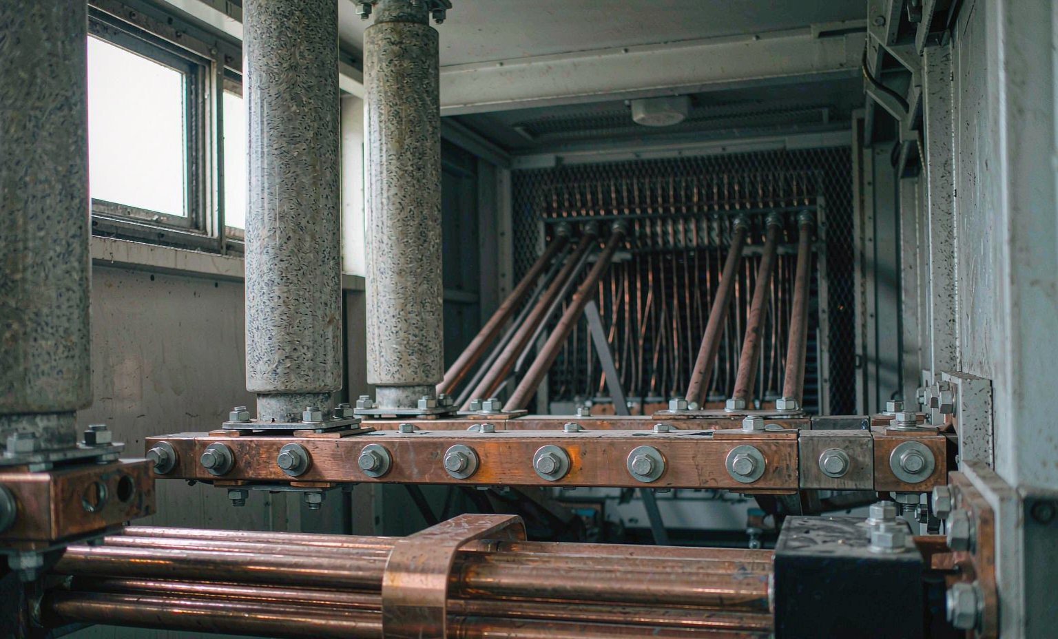
Take one bolted joint, small enough to cover with a hand. Six 200 x 8 mm copper bars land on a terminal pad carrying 10,000 A. After torqueing, the joint measures 12 micro-ohm. Run it: P = I²R = 10,000² x 0.000012 = 1,200 W. One joint putting out the heat of a small space heater, inside a chamber already above ambient, with a dozen more in the same run. Nothing in the transformer rating predicted it.
On a rectifier transformer, secondary current is not a scaled copy of the DC output. A distribution winding sees a sinusoidal current that follows the load. A rectifier secondary sees a quasi-square waveform with commutation notches, so the RMS value that sizes the conductor and the harmonics that drive losses are separate problems. Because the transformer and the rectifier usually come from different vendors, somebody has to own the interface.
Start the design at the exit, not the winding
Most specifications describe the transformer carefully, then add one line about terminations. That line is where the risk sits. Once the secondary leaves the terminal chamber, current is at its maximum and geometry is most constrained: fixed pad drilling, fixed chamber volume, and support against short-circuit forces that scale with the square of the current. Draw the exit, with dimensions, before the rating is frozen. Our notes on how to design a transformer for high current applications cover the machine level; this stays with what happens afterwards.
What 10,000 A asks of a cross-section
Current density is the first number to settle. Six bars of 200 x 8 mm give 1,600 mm² each and 9,600 mm² as a group, so at 10,000 A that is 10,000 / 9,600 = 1.04 A/mm². Enclosed high-current busbar is commonly designed between 1.0 and 1.6 A/mm². Eight bars of the same section give 12,800 mm² and 10,000 / 12,800 = 0.78 A/mm². More bars is not automatically better: every parallel bar needs joints at both ends, and every joint can grow resistance. The designer balances density, how evenly current divides, the cooling of a rectifier transformer, and how many joints they hand to an installer.
Skin depth, and why several thin bars beat one thick bar
Alternating current does not use the whole cross-section. The depth it reaches is d = sqrt(rho / (pi x f x mu0)), with rho = 1.68 x 10^-8 ohm.m for copper at 20 degrees C and mu0 = 4 x pi x 10^-7 H/m. At 50 Hz the denominator is pi x 50 x 4 x pi x 10^-7 = 1.974 x 10^-4, giving d = sqrt(1.68 x 10^-8 / 1.974 x 10^-4) = sqrt(8.51 x 10^-5) = 9.2 mm. The same arithmetic at 60 Hz gives 8.4 mm.
An 8 mm bar is thinner than one skin depth at both frequencies, so most of the section works. three skin depths, and its middle contributes far less than its weight suggests. Packs of thin laminated bars replace one heavy section for exactly this reason, and a design proven at 50 Hz deserves a fresh check before 60 Hz service.
The joint is the component that decides whether it runs cool
At 12 micro-ohm and 10,000 A a joint dissipates 10,000² x 0.000012 = 1,200 W. Let it degrade to 50 micro-ohm through a slack bolt, an oxidised face or a missing washer and it dissipates 10,000² x 0.00005 = 5,000 W in the same volume. Because loss follows the square of current, a joint comfortable at 8,000 A runs (10,000 / 8,000)² = 1.56 times hotter at 10,000 A, which is why uprates expose joints that were never a problem.
Four things prevent it. Contact faces flat, clean and tin or silver plated, so an oxide layer does not build. A conical washer in the stack, so pressure holds as copper creeps. Torque set to the designer’s value for that bolt grade and size, then re-checked after the first heat cycle rather than assumed to have held. And a millivolt drop reading per joint at rated current, compared joint against joint.
Flexible links, supports, and keeping steel out of the field
Between the terminal and the fixed busbar there should be a flexible laminated or braided link. It absorbs thermal growth, and it keeps core magnetostriction vibration, which runs at twice supply frequency, out of the bushing and its seal. Supports need equal care. Magnetic steel in a high-current field carries induced eddy currents and heats, and any plate passing right around a conductor becomes a shorted turn. Use non-magnetic inserts where the field is strong, and a slot in any plate that would close a loop. Clearances should arrive with the drawings and stay on site, because a brace fitted to stop a rattle can undo the calculation.
What we need before the secondary can be designed
Most of the delay happens before anyone draws a bar. Every item below moves the design:
- network voltage and frequency, 50 Hz or 60 Hz
- DC voltage and DC current, plus the duty class
- rectifier connection and pulse number
- tap changing method and range, if any
- cooling method, and indoor or outdoor installation
- altitude and ambient temperature at site
- which way the bars leave, and the mating interface
- access for torqueing and later infrared surveys
Type-test and certification requirements are supported per project, not assumed from a standard package. Standard arrangements are quoted on a 30-day build with a two-year warranty. The rectifier transformer range is where to start if duty is still being defined, the power transformer product range lists the wider catalogue, and our notes on the high current rectifier transformer take the same currents from the winding side.
Frequently Asked Questions
Why is the secondary rated in kA when my process is specified in DC amps?
On a three-phase bridge the valve-side winding carries 120 degree blocks, so its RMS is the square root of 2/3 times DC current, about 0.82 x Idc: 8,000 A DC is roughly 6,530 A in the winding. The factor depends on the connection and pulse number, so quote the DC current and let the maker derive the secondary figure.
Can I use single-core cables instead of busbar on the secondary?
At lower currents, yes, and usually cheaper. As current climbs you need more cables in parallel, and grouping derating, termination space and uneven sharing return as problems spread over more components. Busbar with a flexible link keeps joint count down and gives a place to read millivolt drop. For awkward routes, busbar to a marshalling point then cable is the answer.
What should be checked at commissioning?
Three things. A millivolt drop reading across every joint near rated current, compared joint against joint. An infrared survey once the unit reaches thermal equilibrium, at comparable load. And a re-torque of the joint stack after the first thermal cycle, since copper and insulation relax under first heat. Keep all as a baseline.
Talk to Our Engineering Team
Send the rectifier duty, the DC voltage and current, the pulse number, and a sketch of where the bars have to land. We will come back with a proposed secondary arrangement and a quotation on FOB, CFR or CIF terms. Email info@xsdfftransformer.com, call +8615867897761, or message WhatsApp +852 5416 2620.