Put a vector group on a drawing and most people read it as a label. Dyn11 states something exact: the secondary vector sits at eleven on a clock face, each hour is 30 degrees, so 11 x 30 = 330°, which is 30° of lead once you wrap past twelve. That is the reason a twelve-pulse rectifier is inexpensive to build. One secondary wound star, one wound delta, the same turns ratio, and the two outputs land half an hour apart on the clock.
The difficulty arrives when the duty asks for more. Twenty-four pulse needs groups 15° apart, eighteen pulse needs 20°, and neither falls out of a plain star and delta pair. At that point the angle has to be manufactured. The rectifier transformer harmonics piece covers what those groups cancel and why the arithmetic works; this one is about how the displacement is produced, and what happens when it is not.
Where 30 degrees comes from, and what it will not give you
Two secondaries with the same turns ratio, one connected star and one connected delta, produce voltage sets displaced by 30°. This follows from the connection rather than from design cleverness: in a star winding the line-to-line voltage leads its own phase voltage by 30°, and in a delta it does not. Feed each into a six-pulse bridge, join the bridges on the DC side through an interphase transformer, and the fifth and seventh harmonics of the two groups work against each other. The mechanism is set out in our note on how a rectifier transformer works.
What it costs is nothing extra in copper. What it does not offer is choice. A star and delta pair delivers multiples of 30° and nothing between them.
The pulse number decides the spacing
Count n as the number of six-pulse groups feeding the bus. With them evenly spaced, the displacement needed between neighbours is 60 / n degrees. Twelve pulse is two groups and 60 / 2 = 30°, supplied free by the star and delta pair. Eighteen pulse is three groups and 60 / 3 = 20°. Twenty-four pulse is four groups and 60 / 4 = 15°. Neither 20° nor 15° appears in a standard vector group, and that single fact drives every decision after it.
Making angles that standard vector groups do not offer
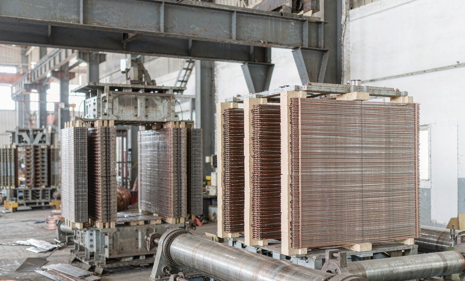
Intermediate angles are built with an extended delta, sometimes called a hexagon connection, or with a zig-zag winding, also known as an interconnected star. In an extended delta, each phase carries additional turns beyond the delta corner and the output terminal is taken from the far end of that extension. The output vector then lands between the angles a plain delta and a plain star would give, at a position set by how many extension turns there are relative to the main winding: zero extension gives a delta, zero main section gives a star. Zig-zag windings reach the same outcome by splitting each phase across two limbs.
Two practical points follow. For a small angle like 7.5° the extension carries only a small fraction of the total turns, so it is an addition to the main winding rather than a second transformer, although it does have to be wound for the full line current. And every output has to come out at the same magnitude as its neighbours, within the tolerance the design allows, because bridges that see unequal voltage will not share current evenly however accurate the angle is.
Putting two units on one DC bus
A usual twenty-four pulse arrangement is two transformers, each internally a star and delta pair, sharing one bus. On its own each unit is a twelve-pulse set with secondaries 30° apart. To reach 15° spacing the two units are rotated relative to each other on the primary side, with an extended delta.
The symmetric version is easiest to follow. Rotate one unit’s primary by minus 7.5° and the other’s by plus 7.5°. The first unit’s secondaries then sit at minus 7.5° and plus 22.5°, because 30° separates them internally. The second sits at plus 7.5° and plus 37.5°. Sorted, the four groups are minus 7.5, plus 7.5, plus 22.5 and plus 37.5, with 15° between each neighbour. That is twenty-four pulse from two machines that are otherwise identical.
What a rotation error looks like on site
Phase shifting faults rarely announce themselves. Swap two primary phases on one unit and it still energises, still measures the correct secondary voltage when read on its own, and still delivers DC. Only the angle is wrong, so harmonics that were meant to cancel now reinforce. The symptoms are indirect: a filter sized correctly runs hot, protection trips on a harmonic setting nobody expected to reach, or measured distortion sits nearer six pulse than twelve.
Two more errors produce the same family of result. A delta closed with reversed polarity puts one group 180° from where it belongs. And a replacement bought years later may carry the right rating with the wrong vector group, because the original was part of a matched set. Before closing onto the bus, confirm that corresponding secondary line voltages measure equal, and that the angle between them matches the drawing.
What to specify
The displacement is part of the equipment definition, not a preference to settle later. Give us the pulse number, whether one transformer or several share the bus, the DC voltage and current, network voltage and frequency, and the groups each unit must provide with the intended displacement, or the vector groups if you know them. Type-test and certification requirements are supported per project, not assumed from a standard package. If you are choosing between configurations, our guide to selecting a rectifier transformer takes the same decisions from the procurement side, and the rectifier transformer range shows the usual arrangements.
Frequently Asked Questions
Can I get 12-pulse operation from a single transformer?
Usually yes. One unit with two secondaries, one star and one delta, feeding two six-pulse bridges joined through an interphase transformer, gives twelve pulse on one tank. Separate units are chosen when the rating exceeds one tank, when transport limits beat the dimensions, or when the plant wants one unit serviceable while the other runs.
Do all units on a shared DC bus need the same vector group?
They need complementary vector groups, not identical ones. Each member of a multipulse set contributes a specific displacement. Trouble comes from adding a unit years later that matches the rating but not the angle. Check the displacement before paralleling onto an existing bus.
Does the phase shift reduce the DC output voltage?
No. Each bridge contributes close to the DC voltage it would produce alone, because the shift moves the waveforms in time without changing amplitude. What it changes is ripple and harmonic cancellation on the AC side. Output magnitude is set by secondary voltage and firing angle, not by rotation.
Talk to Our Engineering Team
Send the pulse number, whether one unit or several will share the bus, and the DC voltage and current. We will come back with the secondary and vector arrangement and a quotation on FOB, CFR or CIF terms. Email info@xsdfftransformer.com, call +8615867897761, or message WhatsApp +852 5416 2620.