A rectifier transformer does more than change voltage. It sets the pulse number of the rectifier it feeds, and that one number decides how much harmonic current your plant sends back into the supply network.
Get it wrong and you will be buying filters later, derating other equipment, or explaining distortion to your utility. Get it right and harmonic mitigation becomes a design decision instead of a repair job.
This guide explains why pulse number matters for rectifier transformer harmonics, compares 6-, 12- and 24-pulse arrangements using published drive data, and lists what belongs in a specification.
Why a rectifier transformer produces harmonics
A rectifier bridge is a non-linear load. Current is drawn in short pulses rather than a smooth sine wave, so the line current contains a family of frequencies that are whole-number multiples of the supply frequency. These are the characteristic harmonics.
They do not stay inside the rectifier. Harmonic currents travel back through the transformer into the plant distribution system and the utility network, where they cause:
- Extra eddy-current and stray losses in transformer windings, which raise winding temperature and shorten insulation life
- Overheating and premature failure of power factor correction capacitors
- Additional heating and torque ripple in motors
- Nuisance tripping of protection, and distortion of the supply voltage seen by other users
Because the transformer is the interface between the DC process and the AC network, its winding arrangement is the most effective place to control harmonics. The design lever is the pulse number.
The rule that decides everything: h = n × p ± 1
Characteristic harmonics generated by a rectifier follow a fixed relationship:
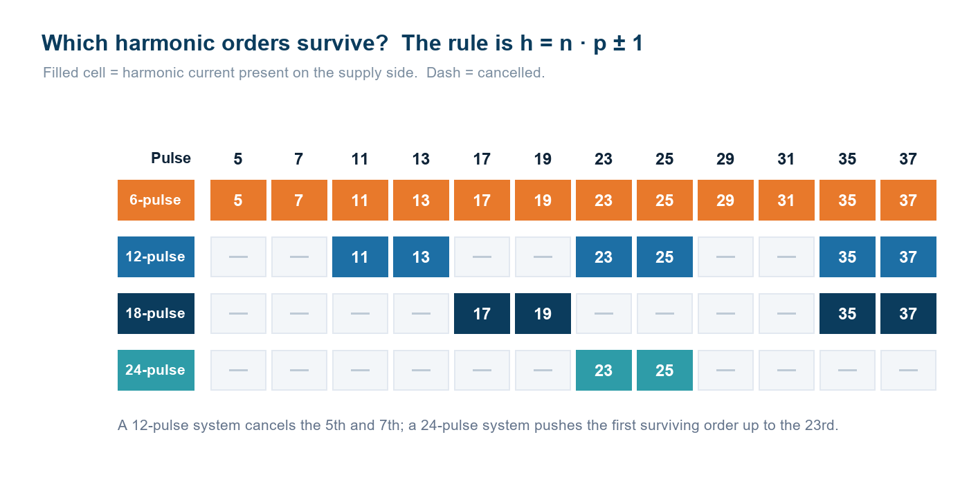
h = n × p ± 1
where h is the harmonic order, p is the pulse number and n is any positive integer.
For a 6-pulse bridge, p = 6, so the orders are the 5th, 7th, 11th, 13th, 17th, 19th and so on. Raise the pulse number and the whole family shifts upward: a 12-pulse system produces the 11th, 13th, 23rd, 25th …, while a 24-pulse system starts at the 23rd and 25th.
That is the entire idea behind multipulse rectification. You are not removing distortion — you are moving it to higher frequencies, where amplitudes are lower and any filter you still need is smaller and cheaper.
Comparing 6, 12 and 24-pulse designs
| Pulse number | Transformer | Characteristic orders | What it means in practice |
|---|---|---|---|
| 6 | Two-winding | 5, 7, 11, 13, 17, 19 … | All low-order harmonics present. Needs an AC or DC choke at minimum. |
| 12 | One three-winding, 30° shift | 11, 13, 23, 25 … | 5th and 7th cancelled at the primary. The standard choice for medium voltage fed rectifiers and drives. |
| 24 | Two three-winding, 15° shift | 23, 25, 47, 49 … | Cancelled up to the 19th. For very large single drives or large multi-drive installations. |
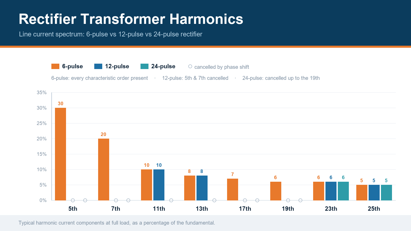
The measured improvement is substantial. On a 6-pulse bridge without a choke the 5th harmonic current typically reaches 50–60% of the fundamental, with the 7th between 40 and 50%. Adding an AC or DC inductor drops the 5th to roughly 30% and the 7th to about 12%. A 12-pulse arrangement with a double-wound transformer brings the 5th into single figures and the dominant remaining orders become the 11th and 13th.
The trade-off is cost and complexity. Taking a 6-pulse bridge as the baseline, a 12-pulse solution typically costs around twice as much, and a 24-pulse solution roughly two and a half times. That is why multipulse supply is usually applied above about 400 kW per drive, and why it assumes a dedicated transformer fed directly from the medium voltage network.
Where the process needs a very high DC current — our rectifier transformers are engineered for secondary currents up to 10,000 A — the pulse number decision has to be made together with the vector group and the cooling design, not after them.
How the 30° phase shift cancels the 5th and 7th
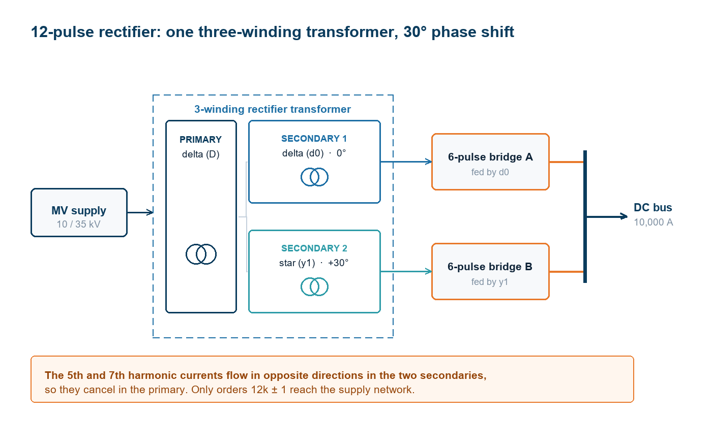
A 12-pulse rectifier needs a transformer with three windings: one primary and two secondaries. The classic arrangement is a delta primary with a delta secondary and a star secondary.
The star connection introduces a 30° electrical displacement between the two secondary voltages. Each secondary feeds its own 6-pulse bridge, so each one individually carries the full family of 6-pulse harmonics — including the 5th and 7th.
The cancellation happens on the primary side. Referred to the primary, the 5th and 7th harmonic currents from the two secondaries are displaced by 180° and therefore subtract. They circulate between the two secondary windings instead of flowing out to the network. Only the orders both secondaries produce in phase — 12k ± 1, meaning the 11th, 13th, 23rd and 25th — reach the supply.
Two practical consequences follow from this:
- The secondary connections are not interchangeable. The phase shift is a design feature. A rewound or modified secondary changes the harmonic performance of the whole installation.
- The two bridges must be loaded similarly. If load is badly unbalanced between the secondaries, cancellation degrades and low-order harmonics reappear on the supply side.
Three cheaper levers to try before raising the pulse number
Multipulse transformers work, but they are not the only option and they are not always the best value. Before committing:
- Add an AC or DC choke. The cheapest single measure available. On a 6-pulse bridge it cuts the 5th harmonic from roughly 60% to about 30% of the fundamental.
- Check the short-circuit ratio. The ratio of supply short-circuit power to connected equipment rating determines how much voltage distortion a given harmonic current actually produces. A plant on a strong network can tolerate a 6-pulse rectifier that would be unacceptable on a weak rural supply.
- Consider passive or active filtering. A tuned passive filter can target the dominant orders at lower cost than a 24-pulse transformer, though it introduces a parallel resonance risk that has to be studied.
The correct sequence is to calculate the harmonic current spectrum and the resulting voltage distortion at the point of common coupling, compare it against the applicable limit, then choose the least-cost measure that complies. Starting from a pulse number and working backwards usually costs more.
Choosing the pulse number for your project
Work through these questions in order:
- What is the DC load, and how continuously does it run at full rating? A duty cycle that rarely reaches full load changes the economics.
- What is the short-circuit capacity at the connection point, and what harmonic distortion already exists there?
- Which limit applies — IEEE 519, the IEC 61000 series, or a national standard such as GB/T 14549 for plants connected to the Chinese grid?
- Is the rectifier transformer fed directly from the medium voltage network, or from a low voltage busbar? Multipulse arrangements assume a dedicated MV feed.
- What is the total installed cost of each option, including filters, floor space, cooling and additional switchgear?
In most industrial projects the answer settles at 12-pulse. It removes the two harmonics that cause the most trouble, needs one special transformer rather than two, and is the arrangement most utilities accept without demanding a detailed harmonic study.
What to specify for a multipulse rectifier transformer
A specification should state, at minimum:
- Network side: rated voltage, number of phases, frequency, and the fault level at the connection point
- Pulse number, number of secondary windings, and the vector group and phase displacement of each
- DC side: rated DC voltage and current, current waveform, and the method of voltage control — on-load tap changer, off-circuit taps or thyristor control
- Impedance, including the impedance between the two secondary windings
- Harmonic current content the transformer must carry, plus the resulting additional losses and temperature rise. Harmonic currents raise winding losses well beyond the 50 Hz value
- Cooling method and the ambient conditions it is rated for
- Tests: routine tests, a temperature rise test using the actual harmonic spectrum where practical, and any witnessed or third-party inspection the end user requires
Our engineering team designs rectifier transformers with custom vector groups, phase displacements and cooling to match a specific DC duty, and every unit is routine tested with documented reports before shipment.
Next step
If you are specifying a rectifier transformer for an electrochemical line, an electrolysis plant or a DC arc process, send us the DC duty — voltage, current, duty cycle and the harmonic limit you have to meet. We will come back with a proposed pulse number, vector group and rating, together with the reasoning behind it.
Read more about how to select a rectifier transformer, or contact our engineering team to discuss your application.