On a factory acceptance test day the readings usually pass. The column that deserves attention is the one beside them: the serial number, the tapping position, the winding temperature, and the reference temperature each result was corrected to. A load loss measured at 28 °C cannot be compared with a guarantee stated at 75 °C, and a ratio recorded on the wrong tap describes a different transformer.
IEC 60076-1 splits tests into three groups, and the distinction decides what a witness is entitled to see. Our testing page shows where these checks sit in the build; this article takes the routine list line by line, since those are the measurements made on every unit before it ships, and the ones a buyer can reasonably ask to watch.
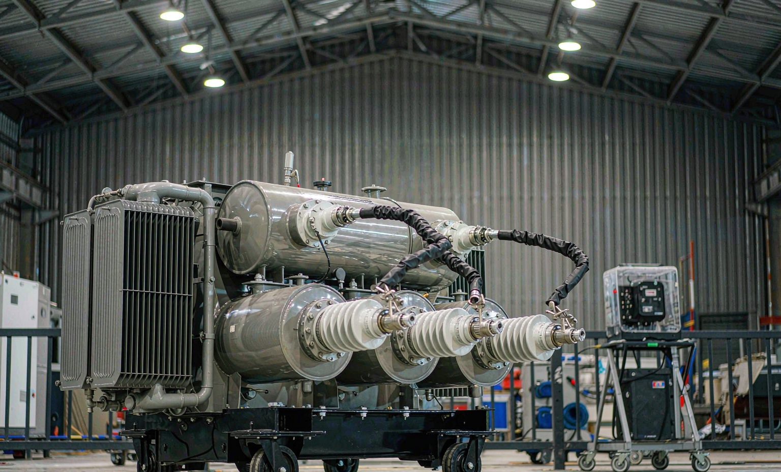
Routine, type and special tests: three different obligations
Routine tests are performed on every transformer. Type tests are performed once on a representative unit to prove a design, and special tests are done only when the contract asks for them — a temperature rise test or a lightning impulse test, for example. A buyer sometimes asks why an impulse test is not repeated on each unit; the answer is that it is a type test on the design, not a routine test on the individual machine.
That split also explains the paperwork. A type test report carries a design or type reference, while a routine report should carry the serial number of the unit in front of you. If the two are bound into one document without that link, ask which pages were measured on this transformer. Certification and type-test documentation are supported per project rather than assumed from a fixed package; send the standards and reports your specification calls for and we will confirm what can be arranged.
Winding resistance and ratio: the two baselines
Winding resistance is measured by the d.c. voltage-drop method, R = U / I, on each winding and each tapping. Copper changes resistance with temperature, so IEC 60076-1 corrects the reading to a reference temperature using R75 = Rt × (235 + 75) / (235 + t), with 235 as the copper constant. Take a reading of 1.240 Ω at 28 °C and the correction is 1.240 × 310 / 263 = 1.462 Ω. Record the winding temperature at the moment of measurement; without it the number cannot be checked, and a warm winding after a previous test will read high for no other reason.
Voltage ratio is then measured at every tapping position together with the vector group — a Dyn11 unit, for instance, is confirmed by the phase displacement, not by the ratio alone. The standard sets a tolerance on ratio (commonly ±0.5 % on the principal tapping). A ratio that passes on the principal tapping but drifts on an extreme tap points to a turns count or a lead connection that needs resolving before the tank is closed, when it is still a cheap correction.
Impedance and losses: three numbers with different corrections
Short-circuit impedance and load loss come from the same test: one winding is shorted and voltage is raised on the other until rated current flows. Impedance is Uk% = (Usc / Ur) × 100, so 550 V applied on a 10,000 V winding to reach rated current gives 5.5 %. That figure sets the fault level downstream and the voltage drop under load, and it is the value that has to match if two units are to share a bus in parallel rather than one taking more than its share.
Load loss is split into an I²R part that rises with temperature and an additional stray-loss part that falls with it, so the measured value is corrected to the reference temperature before it is compared with a guarantee. No-load loss and no-load current are measured at rated voltage with the secondary open: they describe the core, not the load. How those losses are capped by efficiency regulation is set out in our article on transformer efficiency standards, and the same two numbers feed a total-cost comparison at bid stage, where the cheapest purchase price is not always the lowest lifetime cost.
Applied and induced voltage: what each dielectric test reaches
The applied-voltage test (separate-source a.c. withstand) puts a power-frequency voltage between windings and from each winding to earth, typically for one minute. It checks the main insulation to ground and between windings. It does not stress the insulation between turns, because the whole winding sits at essentially the same potential during the test.
The induced-voltage test closes that gap. Voltage is applied from the low-voltage side at raised frequency so the core does not saturate: flux density is proportional to V / f, so at rated 50 Hz we have Ur / 50 = 0.02 Ur per hertz, and applying 2 Ur at 100 Hz gives 2 Ur / 100 = 0.02 Ur per hertz — the same flux with twice the voltage. Run that 2 Ur at 50 Hz instead and the flux doubles, which is why test sets use 100 Hz and above. Insulation resistance and polarisation index are commonly logged on the same day, though they belong to installation and commissioning practice rather than the IEC 60076 routine list.
What a buyer’s witness should actually check
Start with identity: the nameplate serial number must match the routine report. Then check the tapping position, the winding temperature, the reference temperature used for corrections, and the calibration dates of the measuring equipment. Ask to see the accuracy class of the instrument chain, because a ratio tolerance of half a per cent is meaningless if the bridge itself is out of calibration.
Finally, agree the hold points before the test day and record any deviation in writing instead of accepting a verbal pass. Our quality control page describes how these records are kept, and the power transformer range shows the units the routine list applies to. If your specification adds special tests or third-party witness, send the standards and witness points your project requires; those are handled per project rather than claimed from a fixed package. Delivery is 30 days from approved drawings and the warranty runs 2 years. The same checklist in specification form is in our special transformer specification guide.
Frequently Asked Questions
Is a type test report enough to accept a unit?
No. A type test proves a design; routine tests are performed on every individual unit. Ask for both, with the routine report tied to the serial number of the transformer being shipped.
Why must load loss be corrected to a reference temperature?
Because winding resistance rises with temperature, so the I-squared-R part of load loss changes. Comparing a measured value at 28 degrees with a guarantee stated at 75 degrees without correction can make a compliant unit look non-compliant.
Are certification and third-party witness provided as standard?
They are supported per project. Send the standards, tests and witness points your specification calls for and we will confirm what can be arranged before any order is placed. Nothing is claimed from a fixed certificate package.
Ask for the Test Records
Send the standards, witness points and any special tests your project requires. Email info@xsdfftransformer.com, call +8615867897761, or message WhatsApp +852 5416 2620. The same request can be sent through our enquiry page.