A transformer for a solar plant or a battery energy storage system carries the same kVA as a factory unit and is designed differently in almost every respect. The load is not a motor or a process line. It is an inverter, it runs to a daily cycle instead of a production schedule, and on a storage site it pushes power in both directions.
Where the transformer sits in the system
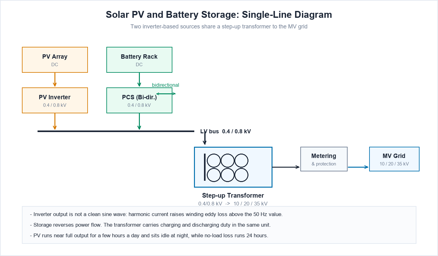
PV modules and battery racks are DC. An inverter converts that to AC at a low voltage, commonly 400 V or 690 V, and larger central inverters at 800 V class. The transformer steps that up to the site’s medium voltage, typically 10, 20 or 35 kV depending on the country and the grid connection agreement, and the MV side runs to the point of connection.
On utility-scale sites the transformer often arrives integrated with the switchgear in a compact enclosure or a skid, which constrains its dimensions and its cooling arrangement before any electrical decision is made.
Why the inverter changes the design
An inverter does not draw or deliver a clean sine wave. Its output current contains harmonic components on top of the fundamental, and those components produce additional eddy losses in the windings and stray losses in nearby steel, above what the 50 Hz calculation shows.
Grid codes limit how much distortion the inverter may export, so the spectrum is bounded, but bounded is not the same as absent. A transformer sized purely on kVA and fundamental-frequency losses runs hotter than its rating sheet suggests, and the margin has to be designed in rather than discovered during commissioning.
There is also a direct-current consideration. Standards such as IEEE 1547 limit the DC injection an inverter may feed into the network, but even a small DC component biases the core. The design needs the margin to tolerate it without pushing the core into saturation.
Bidirectional power flow on storage sites
A battery site charges and discharges through the same transformer. The unit therefore sees full-rated current in both directions, and the cooling design has to assume continuous operation in either direction rather than occasional peaks.
Two practical consequences follow. The vector group and any earthing arrangement have to suit both operating modes. And the loss evaluation should count both the charging and discharging paths, because a round-trip efficiency calculation penalises transformer losses twice.
The duty cycle, and why no-load loss carries more weight
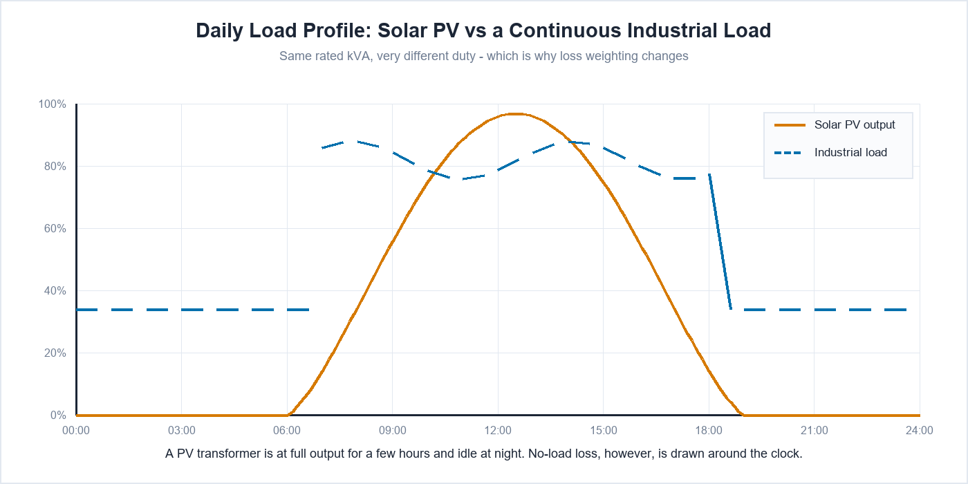
A PV transformer runs near full output for a few hours around midday and carries close to nothing overnight. A storage transformer follows the dispatch schedule instead, which may mean one or two full charge-discharge cycles a day.
The no-load loss, however, is drawn whenever the transformer is energised, and on a renewable site it stays energised around the clock whether the sun is up or not. Over a year, the no-load loss of a lightly loaded unit can account for more energy than the load loss does. That shifts the economic weighting towards a low P0 design, and it is the opposite of the weighting you would apply to a transformer that runs heavily loaded on two shifts.
Ambient, enclosure, and site conditions
- Temperature. Desert sites reach ambient levels well above the 40 °C basis in general-purpose designs, and the rating has to be corrected for it.
- Sand and dust. Enclosure protection and sealing follow from the site, not from a default IP number.
- Coastal and offshore. Salt spray pushes the specification towards sealed encapsulated windings or protected enclosures.
- Altitude. Air density falls with height, and with it the cooling and the clearances.
Liquid-filled or cast resin for a renewable site
Both appear. Cast resin suits the indoor, containerised, and fire-constrained applications: rooftop plants, commercial storage cabinets, and any site where an oil containment would be difficult. Liquid-filled units remain common on open-air utility sites, where the better cooling and the lower cost per kVA work in their favour and there is room for containment.
The choice is usually settled by the site layout and the fire strategy before it is settled electrically.
What to send us
- Inverter or PCS output voltage, and the number of units paralleled on one transformer.
- MV voltage and the grid connection requirements that apply.
- Expected duty: the site’s generation or dispatch profile, not just the peak.
- Harmonic spectrum of the inverter output, if the manufacturer publishes it.
- Ambient temperature, altitude, dust and salt exposure.
- Enclosure, footprint, and access constraints, particularly for skid or container mounting.
See the dry type transformer range, the cast resin transformer range, or contact us with the site data.
Related Products
Related Applications
Request a Custom Quote
Need a custom transformer for your application? Send us your technical requirements and our engineering team will provide a custom solution within 24-48 hours.
How this is packaged on real projects
On most sites the unit described here is not installed on its own. It goes into an assembly that includes the incoming switching, protection and outgoing feeders, which you can see on the solar power plant substations, wind farm substations and compact substations pages.
Frequently Asked Questions
What should be confirmed before ordering a transformer for storage projects?
System voltage and frequency, fault level at the point of connection, the load with its duty, and the site conditions including ambient range and indoor or outdoor placement. With those settled the rest of the specification follows.
What changes when the transformer is part of a renewable or storage project?
Power flows in both directions in storage applications, and inverter-fed supplies carry harmonics. Protection coordination and winding configuration are decided with that in mind rather than from a standard distribution template.
Does the intermittent duty affect the transformer specification?
It can. A unit that runs near full load for a few hours and sits at low load otherwise has a different loss profile from one at steady load. Ambient temperature and enclosure conditions often matter more here than the average loading.
Which standard applies, and is it certified?
The applicable standard and clause set are agreed against your project specification before production starts. Where a project names IEC 60076 for the transformer, we work to those clauses and the routine test report ships with the unit.
What do you need from us to quote?
The single-line diagram or a description of the application, the voltages, the load with its duty, the site conditions, and any standard the project specifies. Send what you have – if something is missing, it can be worked out together rather than delaying the enquiry.